
Knowby
Z2 & ZJ31 Holder Installation Tutorial
Step-by-step guide to assembling and installing the Z2 & ZJ31 self-service kiosk, from mounting the table-top brackets through wiring, fitting the mainframe and accessories, and final cable connection. Based on the on-screen installation demo.
1
Step 1 of 20
<p>Hold the display unit ready and lay out the parts for assembly.

On-screen text: &quot;Hold display&quot;</p>

Hold the display unit ready and lay out the parts for assembly. On-screen text: "Hold display"

2
Step 2 of 20
<p>Prepare the recommended tools: an electric drill/driver and a hex key.

On-screen text: &quot;Recommended Tool&quot;</p>

Prepare the recommended tools: an electric drill/driver and a hex key. On-screen text: "Recommended Tool"

3
Step 3 of 20
<p>Install the table-top fixing bracket using M6&#215;14 hexagon socket head cap screws.

On-screen text: &quot;Install the table top fixing bracket — Use M6*14 hexagon socket head cap screws&quot;</p>

Install the table-top fixing bracket using M6×14 hexagon socket head cap screws. On-screen text: "Install the table top fixing bracket — Use M6*14 hexagon socket head cap screws"

4
Step 4 of 20
<p>Secure the table-top fixing bracket using PWM3&#215;8 round-head screws with pads.

On-screen text: &quot;Install the table top fixing bracket — Use PWM3x8 round head with pad screws to fix&quot;</p>

Secure the table-top fixing bracket using PWM3×8 round-head screws with pads. On-screen text: "Install the table top fixing bracket — Use PWM3x8 round head with pad screws to fix"

5
Step 5 of 20
<p>Install the table using M6&#215;14 hexagon socket head cap screws.

On-screen text: &quot;Install the table — Use M6*14 hexagon socket head cap screws&quot;</p>

Install the table using M6×14 hexagon socket head cap screws. On-screen text: "Install the table — Use M6*14 hexagon socket head cap screws"

6
Step 6 of 20
<p>Remove the front and rear bezels of the bracket (used to route the power supply and network cable).

On-screen text: &quot;Remove the front and rear bezels of the bracket — Used to arrange power supply and network cable&quot;</p>

Remove the front and rear bezels of the bracket (used to route the power supply and network cable). On-screen text: "Remove the front and rear bezels of the bracket — Used to arrange power supply and network cable"

7
Step 7 of 20
<p>Install the scale power cord, scale data cable and network cable.

On-screen text: &quot;Install the scale power cord, scale data cable, network cable, power cord&quot;</p>

Install the scale power cord, scale data cable and network cable. On-screen text: "Install the scale power cord, scale data cable, network cable, power cord"

8
Step 8 of 20
<p>Route the other side of the scale power cord and scale data cable through the hole.

On-screen text: &quot;Install other side of scale power cord and scale data cable through the hole&quot;</p>

Route the other side of the scale power cord and scale data cable through the hole. On-screen text: "Install other side of scale power cord and scale data cable through the hole"

9
Step 9 of 20
<p>Install the electronic scale.

On-screen text: &quot;Install Electronic Scale&quot;</p>

Install the electronic scale. On-screen text: "Install Electronic Scale"

10
Step 10 of 20
<p>Install the acrylic fence using PWM4&#215;8 round-head screws with pads.

On-screen text: &quot;Install Acrylic Fence — Use PWM4*8 round head with pad screws&quot;</p>

Install the acrylic fence using PWM4×8 round-head screws with pads. On-screen text: "Install Acrylic Fence — Use PWM4*8 round head with pad screws"

11
Step 11 of 20
<p>Install the table-top fixing bracket using M6&#215;14 hexagon socket head cap screws.

On-screen text: &quot;Install the table top fixing bracket — Use M6*14 hexagon socket head cap screws&quot;</p>

Install the table-top fixing bracket using M6×14 hexagon socket head cap screws. On-screen text: "Install the table top fixing bracket — Use M6*14 hexagon socket head cap screws"

12
Step 12 of 20
<p>Install the warning light: remove the screws, then fit the light.

On-screen text: &quot;Install the Warning Light — Uninstall the screws, install the light&quot;</p>

Install the warning light: remove the screws, then fit the light. On-screen text: "Install the Warning Light — Uninstall the screws, install the light"

13
Step 13 of 20
<p>Install the mainframe: fit M6&#215;16 hex socket screws on the left and right of the bracket.

On-screen text: &quot;Install the Mainframe — Install M6*16 hex socket screws on the left and right of the bracket&quot;</p>

Install the mainframe: fit M6×16 hex socket screws on the left and right of the bracket. On-screen text: "Install the Mainframe — Install M6*16 hex socket screws on the left and right of the bracket"

14
Step 14 of 20
<p>Pass the wire through the hole, hang the host on the installed screws, then fix and tighten the screws.

On-screen text: &quot;Pass the wire line through the hole — Hang the host on the installed screws, fix and tighten the screws&quot;</p>

Pass the wire through the hole, hang the host on the installed screws, then fix and tighten the screws. On-screen text: "Pass the wire line through the hole — Hang the host on the installed screws, fix and tighten the screws"

15
Step 15 of 20
<p>Install the antenna.

On-screen text: &quot;Install the Antenna&quot;</p>

Install the antenna. On-screen text: "Install the Antenna"

16
Step 16 of 20
<p>Install the holder for the hand scanner using PWM3&#215;8 round-head screws with pads.

On-screen text: &quot;Installation of Holder for Handscanner — Use PWM3x8 round head with pad screws to fix&quot;</p>

Install the holder for the hand scanner using PWM3×8 round-head screws with pads. On-screen text: "Installation of Holder for Handscanner — Use PWM3x8 round head with pad screws to fix"

17
Step 17 of 20
<p>Lock the back cover of the bracket.

On-screen text: &quot;Lock the back cover of the bracket&quot;</p>

Lock the back cover of the bracket. On-screen text: "Lock the back cover of the bracket"

18
Step 18 of 20
<p>Connect the scale power cord, data cable, network cable and power cord to the ports.

On-screen text: &quot;Install the scale power cord, scale data cable, network cable, power cord&quot;</p>

Connect the scale power cord, data cable, network cable and power cord to the ports. On-screen text: "Install the scale power cord, scale data cable, network cable, power cord"

19
Step 19 of 20
<p>Check the data cable connections are secure and tidy.

On-screen text: &quot;Data cable display&quot;</p>

Check the data cable connections are secure and tidy. On-screen text: "Data cable display"

20
Step 20 of 20
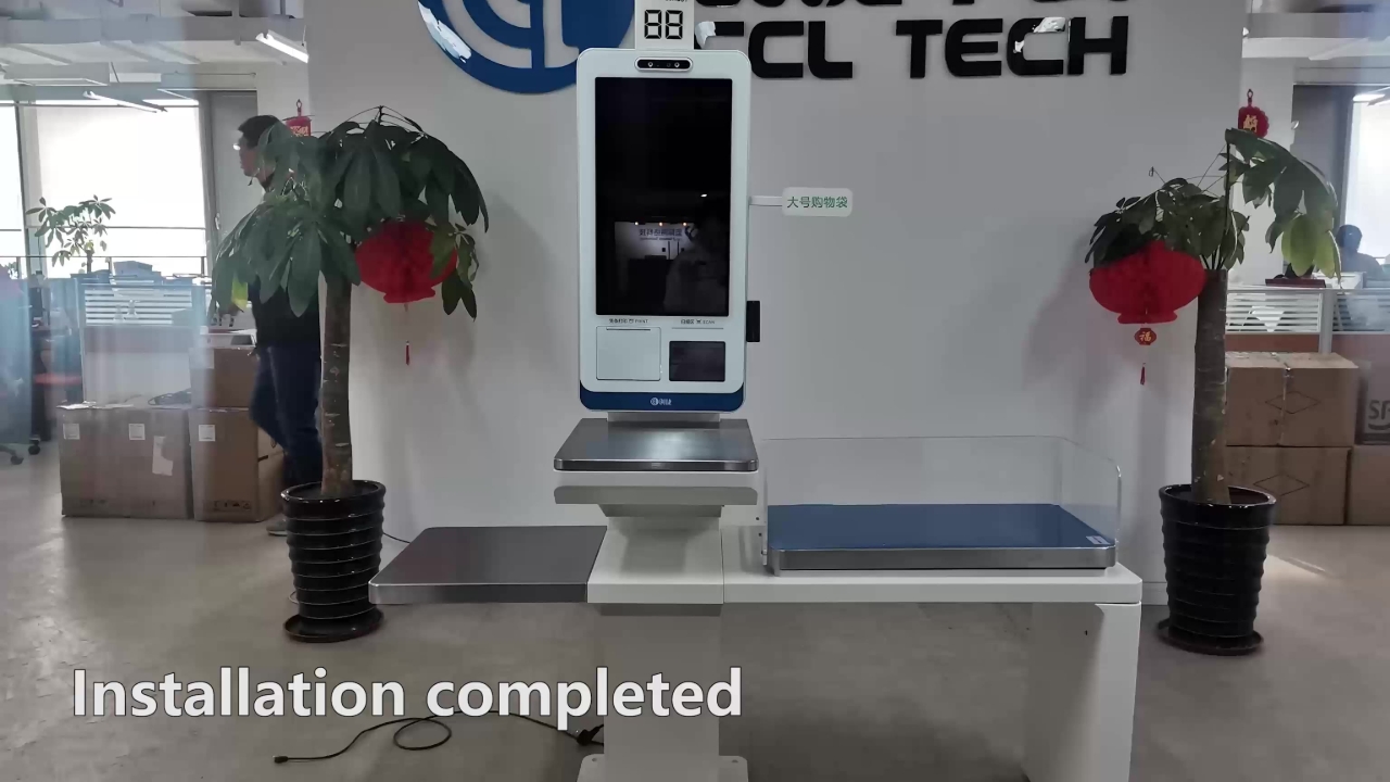
<p>Installation completed.

On-screen text: &quot;Installation completed&quot;</p>

Installation completed. On-screen text: "Installation completed"