Komatsu HD trucks controls and operations
Hello, and thank you for your interest in Komatsu products.
Hello, and thank you for your interest in Komatsu products.
1
Step 1 of 61Today we'll be discussing the controls and operation of Komatsu's HD 465 and HD 605-8 truck.
2
Step 2 of 61So, with that, let's get started.
3
Step 3 of 61We've been discussing the location of the truck controls. Now we will learn how they actually function.
4
Step 4 of 61Some of these controls and operations are directly affected by adjustments that are completed during the commissioning process.
5
Step 5 of 61Ensuring correct adjustments and understanding each function will provide the operator a safe and satisfying experience.
6
Step 6 of 61Let's get started. Let's first start by looking at the three foot pedals. To the far right is the standard accelerator pedal.
7
Step 7 of 61Its movement should be free of any obstructions. Immediately to the left is the right brake pedal.
8
Step 8 of 61This is the operator's normal service brake pedal. When the pedal is depressed, both the front and rear brakes are applied proportionally based on the amount that the pedal is depressed.
9
Step 9 of 61Remember, the front brake application is dependent on the cutoff switch position.
10
Step 10 of 61To the far left is a red brake pedal. This pedal is called the secondary brake pedal.
11
Step 11 of 61Depressing this pedal will apply both the front and rear brakes, regardless of where the front cutoff selection switch is set to.
12
Step 12 of 61This brake pedal is to be used only in the case where there is a brake system issue or failure and the truck cannot be stopped by the normal service brake system.
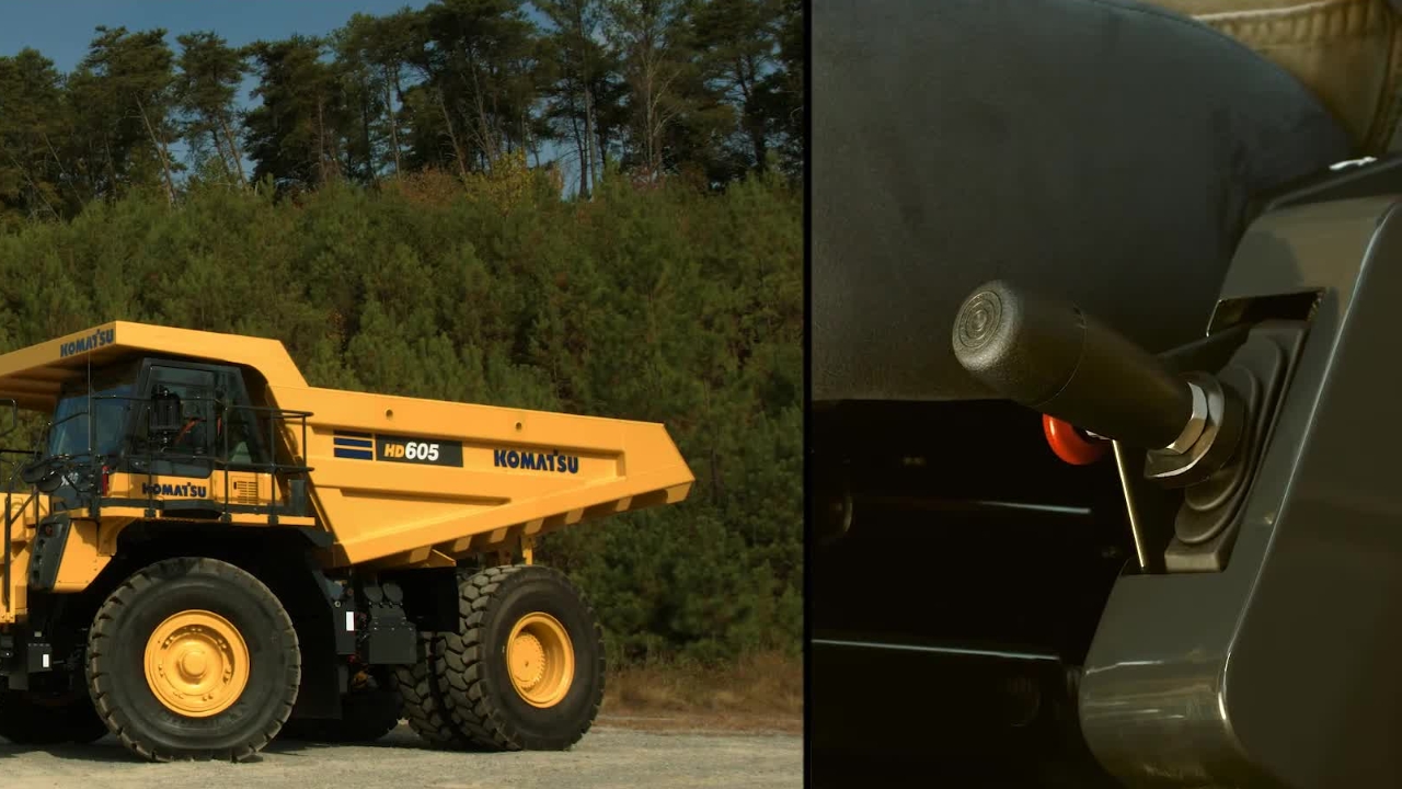
13
Step 13 of 61We have already discussed the four positions of the hoist EPC or electronic proportional control lever.
14
Step 14 of 61We will now review how each of them operate. When the dump lever is pushed all the way down, this applies hydraulic pressure for the bed to be powered down.
15
Step 15 of 61When the dump lever is released, it returns to the float position.
16
Step 16 of 61With the engine running, the normal spring loaded operating position is the float position.
17
Step 17 of 61When the lever is pulled all the way up from the float position, it will pass by the hold position and go into the raise position.
18
Step 18 of 61The handle will stay in the raise position by the detent. At this time, the bed will be going up.
19
Step 19 of 61As the body raises, the float icon on the dash will illuminate.
20
Step 20 of 61If the bed sensors are set correctly at a specific angle, the handle will release and return to the hold position.
21
Step 21 of 61You have the ability to further extend the cylinders, but you must do so by manually lifting the lever.
22
Step 22 of 61Make sure to install the body pins now, if needed, to secure the bed.
23
Step 23 of 61Beside the handle, the lock knob has a pin that keeps the lever in the hold position.
24
Step 24 of 61It must be turned a quarter of a turn for the pin to engage the lever. This is only for locking the handle in the hold position.
25
Step 25 of 61When the bed is to be lowered, push the handle down to the float position.
26
Step 26 of 61With the correct settings, the body should lower to the frame smoothly. The float light should go off and the truck will shift correctly.
27
Step 27 of 61There are four more controls we need to discuss. Two are located on the right side of the steering column.
28
Step 28 of 61These are the manual retarder and ARSC, or automatic retarder speed control.
29
Step 29 of 61Both control handles operate the same system in the rear axle, but do so differently.
30
Step 30 of 61Using the manual retarder control lever, the operator physically pulls the handle down when descending a hill to slow or stop the truck.
31
Step 31 of 61The further the handle is pulled down, the more aggressive the retarder application is applied.
32
Step 32 of 61Any time the retarder lever is applied, the retarder pilot light illuminates.
33
Step 33 of 61You never want to use the manual retarder lever as a parking brake. Remember to always apply the parking brake when exiting the truck.
34
Step 34 of 61The small lever below the manual retarder control lever is the ARSC control.
35
Step 35 of 61ARSC stands for automatic retarder speed control. This is a feature that when enabled and set will automatically apply the retarder to keep the truck at or below the set speed.
36
Step 36 of 61When the system is enabled, the travel speed indicator will show two dashes.
37
Step 37 of 61When driving the truck at the desired downhill speed, press the end of the lever to populate the speed indicator.
38
Step 38 of 61The system will memorize the setting. If the set speed on the indicator needs to be adjusted, raise the handle to increase or push down to decrease.
39
Step 39 of 61To cancel the speed altogether, pull the lever to you for at least two seconds.
40
Step 40 of 61When descending the hill, there are two parameters that must be met for the system to work correctly.
41
Step 41 of 61The operator must be off the throttle and the truck speed needs to be at or below the set retarder speed.
42
Step 42 of 61When this happens, the ARSC ready light will illuminate. If the weight of the load increases the truck speed over the set parameters, the ARSC will proportionally apply the retarder so the truck does not exceed the set speed.
43
Step 43 of 61The gear shift lever allows the operator to select any speed range for the transmission.
44
Step 44 of 61There are seven forward, one reverse, and the neutral gear selections.
45
Step 45 of 61Select the gear shift range with the gear shift lever according to the travel conditions.
46
Step 46 of 61The D, or drive position, is used for normal travel. When D is selected, the transmission will start off in second gear, unless the operator has selected to start in first gear by way of the monitor panel.
47
Step 47 of 61The transmission will shift up to seventh gear automatically based on the travel speed.
48
Step 48 of 61The transmission will be fixed in first gear moving forward with no reverse if the body is raised.
49
Step 49 of 61If any forward position is selected other than the D position, the truck will start off in first gear and shift automatically up to the highest speed that is selected.
50
Step 50 of 61Use these positions when traveling on soft ground. When it is difficult to travel at high speed.
51
Step 51 of 61When starting off on a slope with the bed loaded. Or when traveling downhill.
52
Step 52 of 61The reverse position only operates in first speed. The parking brake switch is right beside the gear shift lever.
53
Step 53 of 61It is used to apply and release the parking brake. By pushing the top of the switch, the parking brake is applied.
54
Step 54 of 61When the parking brake switch is set to the park position, the parking brake pilot lamp lights up on the monitor panel.
55
Step 55 of 61If the gear shift lever is put into any position other than neutral, the centralized warning lamp will light up and the alarm buzzer will sound intermittently.
56
Step 56 of 61When the bottom of the switch is pushed, the parking brake is released. This is the normal travel position.
57
Step 57 of 61For safety reasons, remember that if the engine stops running while the parking brake switch is in the normal travel position, the parking brake will be applied automatically.
58
Step 58 of 61When starting the engine again, set the parking brake switch to the park position and then set it back to the normal travel position to release the parking brake.
59
Step 59 of 61This concludes the controls and operation for Komatsu's HG465 and 605-8 truck.
60
Step 60 of 61If you have any questions or need any additional information, please refer to the operation and maintenance manual located behind the seat.
61
Step 61 of 61Thank you for your interest in Komatsu products.